Audio and Control Matrix HARVEY
HARVEY is a flexible audio and media control matrix and a key component for PA systems and conference systems. It is equipped with analog audio inputs and outputs as well as a large number of different control interfaces and the ideal matrix for conference rooms, home cinemas, museums, educational facilities, multipurpose rooms and theatres.


")


")


Audible
The unit has extensive audio processing functions that can be configured in a way that is tailored precisely to the respective application. These settings can also be saved as a preset and retrieved at the press of a button so that you can change fast between different installation options.
Controllable
Due to the varied control interfaces HARVEY can connect to very different devices and act as a central control unit for audio, lighting and media technology. It converts the data between the interfaces and eliminates the need for additional converters. In addition to the Remote Control RC4 also all established media control systems are suitable for controlling HARVEY and all of the other devices connected to it.
Configurable
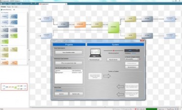
The user interface, the HARVEY Composer, has a simple operating philosophy: The menu structure is clearly arranged, elements are composed in a project by drag & drop and configured immediately in the context menu. That allows you to configure complex projects with only a few mouse-clicks.
User Interface
The user interface of HARVEY is characterized by its clarity and simple structures. It allows for intuitive use and enables every user to develop detailed planning layouts for complex projects in only a few steps.
The HARVEY-Composer's key features:
- Bundling of parallel lines
- Insertion of signal processing per drag & drop
- Layout with automatic adjustment and right-angled wiring arrangement
- Summing up of logical functions into groups
- Separate layers for audio and control paths
- With the HYPERMATRIX® functionality, cross-device projects can be conveniently configured as if it were just a single device.
- Hardware processor load in offline mode
- No compiling necessary
News
HARVEY® Configuration software Release 3.8 with TCP Client Block
The current release 3.8 adds an important control feature to the versatile application possibilities of HARVEY.
With the HARVEY software release v3.8, the TCP client block has now been added. In addition to the UDP client, the TCP client block gives HARVEY the ability to control external devices via TCP network transport protocols. TCP is the standard, especially when used in conference rooms and for controlling projectors, for example, and is preferred over RS232.
Products
HARVEY Pro

HARVEY Pro 8x8

HARVEY Pro is available in various IO configurations, which are appended to the name, e.g. HARVEY Pro 8x8, HARVEY Pro 16x8 or HARVEY Pro 8x8-DA.
In addition to audio signal processing, lighting and media control, HARVEY Pro allows for a flexible response to different market requirements with regard to the number of channels. The audio input and output channels can be scaled in steps of 4, allowing HARVEY Pro to cover the spectrum from small projects with an 8×8 audio matrix to special applications with e. g. 4×24 channels. An appealing wall-mounted remote control for the most important functions completes the product portfolio.
- Control center for audio, light and media equipment
- Flexible number of analog audio channels up to 32
- Digital interfaces Dante and AES
- Excellent audio quality with minimal, constant latency
- Simple configuration of distributed installations with Hypermatrix®
- Control via wall panel or tablet
HARVEY RC4 EU

HARVEY RC4 EU
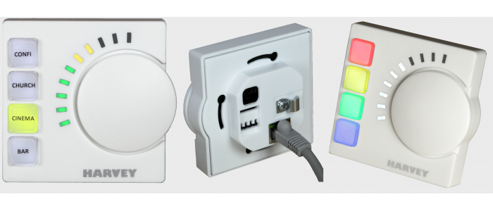
Remote Control in plastic housing for EU flush-mounted box with 60 mm diameter
HARVEY RC4 is a programmable, Ethernet-based wall-mount remote control. RC4 is capable to control presets, audio levels or DMX-lamps. All RC4 LEDs and buttons can be individually customized in their color and brightness.
HARVEY RC4 US

HARVEY RC4 US

Remote control with metal front plate for US 2 gang flush-mounted box in various paint finishes (silver, anthracite, gold)
HARVEY RC4 is a programmable, Ethernet-based wall-mount remote control. RC4 is capable to control presets, audio levels or DMX-lamps. All RC4 LEDs and buttons can be individually customized in their color and brightness.
HARVEY RC12 US

HARVEY RC12 US
Remote control with aluminium silver front plate for US 2 gang flush-mounted in various paint finishes (silver, anthracite, gold)
HARVEY RC12 is a programmable, Ethernet-based wall-mount remote control. RC12 is capable to control presets, audio levels or DMX-lamps and can select channels in a HARVEY device, call up presets or trigger the sending of commands, whether via the serial interface or the IP network, using its 12 freely programmable buttons. All RC12 buttons can be individually customized in their color and brightness.
Downloads
References

Bikini Berlin

Opera Bonn
Palazzo Francesco Melzi d'Eril Milan, Italy

Volkstheater Munich

Changhua County Council Building, Taiwan

Administrative Enforcement Agency Building, Taiwan

San Merchants Building, Taiwan

Peach Blossom Jellyfish Grand Theater Heyuan, China

Meeting Hall of Huiyuantong Building Foshan, China

International Academic Conference Center of Hematology Hospital, Institute of Hematology, Academy of Medical Sciences, China
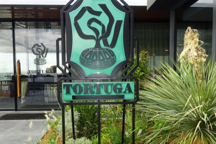
rooftop restaurant TORTUGA, Galeries Lafayette, Paris, France

The Altar of Zhoushan, Ningbo, China
Distribution
HARVEY is a development of DSPECIALISTS digitale Audio- und Messsysteme GmbH. If you are interested in distributing HARVEY or if there is no distributor in your country, please address your inquiry to:
DSPECIALISTS Digitale Audio- und Messsysteme GmbH
Helmholtzstraße 2-9 L
10587 Berlin
Germany
Phone +49-30 467 805-0
Fax +49-30 467 805-99
E-Mail: sales@dspecialists.de
Website: www.dspecialists.com
Belgium and Netherlands:
Match Audio & Vision
Veenweideweg 13a
2957 LD Nieuw-Lekkerland
Netherlands
Phone: +31 184 68 55 76
Fax: +31 184 68 59 82
E-Mail: info@matchav.nl
Website: www.matchav.nl
China:
Jusheng AV Technology(Guangzhou)Co., Ltd.
The Fifth Floor No.1 building
Center 1 Area, Panshan Science and Technology Park
Panyu Da Dao, Panyu District
China
Phone: +86 20 848 812 11
Fax: +86 20 848 812 31
E-Mail: sylvia@jsavtech.cn
Website: www.jsavtech.cn
Finland, Estonia, Latvia, Lithuania:
Seastone Audio Distribution
Helsinki, Finland
iPhone: +358 400 404 190
Tallinn, Estonia
iPhone: +372 5857 6167
Warehouse: EE-11312 Tallinn
E-Mail: hello@seastone.audio
Website: www.seastone.audio
South Korea:
LNS CORPORATION
#10-307 International Distribution Complex
92 LS-ro, Dongang-gu, Anyang-si, Gyeonggi-Do
14117 Südkorea
Phone: +82 50 2552 0734
Fax: +82 50 2449 0734
E-Mail: andy@lnsc.co.kr
Taiwan:
Fantasy Sound International
8F., No. 11, Lane 3, Sec. 1,
Zhongzheng E.Rd. Danshui Dist.
25147 New Taipei City
Taiwan
Phone: +886 2 2626-2788
Fax: +886 2 2626 3788
E-Mail: sales@fantasysound.com.tw
Website: www.fantasysound.com.tw
Italy:
Vicomm Srl
Via Enrico Fermi 8, Zona industriale Est
30020 Noventa di Piave (VE)
Italy
Phone: +39 421 1910220
Fax: +39 421 307845
E-Mail: info@vi-comm.it
Website: www.vi-comm.it
New Zealand:
Sound Choice Pro Audio NZ Ltd
Unit B2, 198 Springs Rd
Hornby
Christchurch 8042
New Zealand
Phone +64 22416378
E-Mail: sales@scpaudio.co.nz
Website: www.scpaudio.co.nz
Switzerland:
Stilus SA
Steigstrasse 2
CH-8610 Uster
Switzerland
Mr. Gianni Amato
Phone: +41 79 824 72 36
E-Mail: g.amato@stilus.ch
Website: www.stilus.ch
France:
3dB sarl
67 Boulevard de Courcelles
75008 Paris
France
Phone: +33 9 50 69 80 66
Fax: +33 9 55 69 80 66
E-Mail: contact@3db.fr
Website: www.3db.fr
Sweden:
AV Nordic
Elinsdalsgatan 15
50433 Borås
Sweden
Phone: +46 33 22 63 80
E-Mail: info@avnordic.se
Website: www.avnordic.se
United Kingdom, Middle East, Africa:
World Marketing Associates
UK OFFICE
PO Box 100,
St Austell, Cornwall
PL26 6YU, England
Phone: +44 20 3390 1207
E-Mail: info@wma.eu.com
Website: www.wma.eu.com
South Africa:
DWR Distribution
Block C Unit 1 Kimbult Industrial Park,
9 Zeiss Road, Laser Park, Roodepoort
PO Box 1130, Honeydew,
2040 Johannesburg, Gauteng
South Africa
Phone: +27 11 794 5023
Fax: +27 11 794 5702
E-Mail: sales@dwrdistribution.co.za
Website: www.dwrdistribution.co.za
Poland:
Lauda Central Europe
ul. Słowackiego 81
80-257 Gdańsk
Poland
Phone: +48 58 555 0660
Fax: +48 58 555 0770
Website: https://laudainstalacje.pl/harvey/
Spain:
RMS Proaudio
Teatro Cartuja Center Building
Avda. Leonardo da Vinci, 11
41092 Seville
Spain
Telefon: +34 955 542 111
E-Mail: info@rmsproaudio.com
Website: https://rmsproaudio.com/
Cyprus:
V Hypersound & Light.
113 Strovolos Avenue
2042 Strovolos / Nicosia
Cyprus
Phone: +357 22767722, +357 22767723
E-Mail: info@hypersound.com.cy
Website: https://hypersound.com.cy
United Kingdom, Ireland:
SCV Distribution
Unit C1 Belcon Industrial Estate
Geddings Road
Hoddesdon
Hertfordshire
EN11 0NT, United Kingdom
Phone: +44 330 122 2500
E-Mail: sales@scvdistribution.co.uk
Website: www.scvdistribution.co.uk
United Arab Emirates:
7Hertz Trading LLC
Light Industrial Unit Phase 1
Warehouse No. 10
Dubai Silicon Oasis,
P.O.Box 487177
Dubai, UAE
Phone: +971 4 379 3259
E-Mail: info@7hertz.net
Website: www.7hertz.net
Lebanon:
7Hertz Trading LLC
#690 Bldg, 9th Floor - Zalka,
Matn Lebanon
Phone: +961 1 893 390
E-Mail: info@7hertz.net
Website: www.7hertz.net